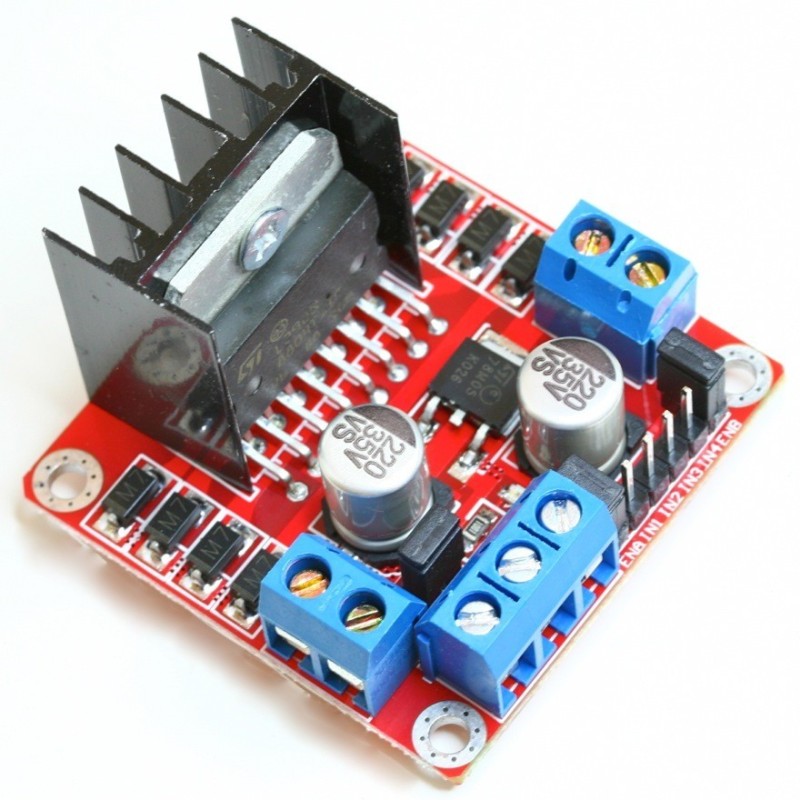


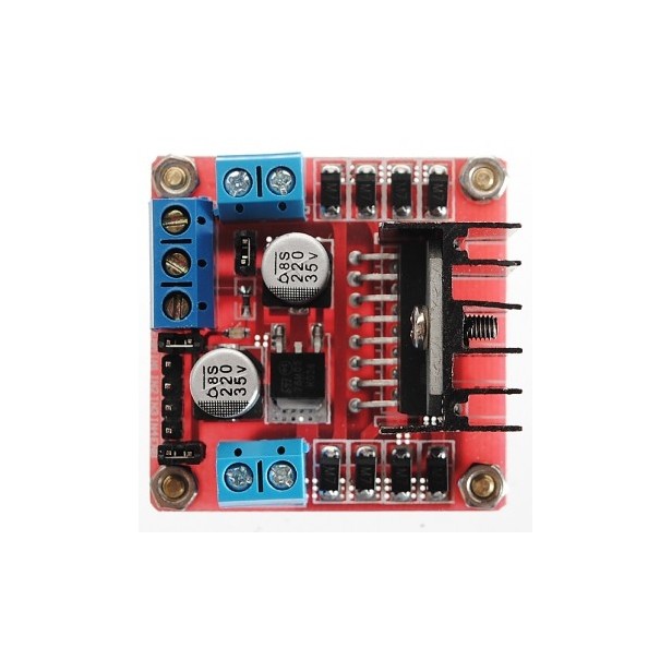

Dual H Bridge DC Stepper Motor Drive Controller Board Module Arduino L298N
The L298N motor controller module (H-Bridge) can directly control 2 motors with a voltage range of 3-30 VDC. It has a 5V interface output
Te quedan 120€ para el envío gratis

24h Delivery

FREE for orders over 120€

Secure payment

Información del producto
The L298N is an H-Bridge, a device used to control DC (direct current) motors or stepper motors. This component is very common in educational robotics projects as it allows for easy control of motor direction and speed.
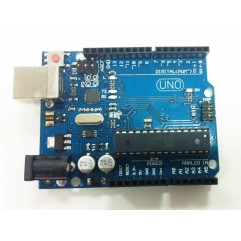
The L298N motor controller module uses an L298N chip that can directly control 2 motors from 3-30 VDC. It has a 5V interface output and supports control from microcontroller systems (such as Arduino) operating at both 3.3V and 5V.
In summary, with this module, you can easily control the speed and direction of your DC motors, and you can also control 2-phase stepper motors.
This module can be easily integrated into mobile platforms, linear mechanisms, etc.
The L298N is an H-Bridge, a device used to control DC (direct current) motors or stepper motors.
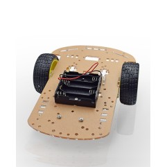
Here is a step-by-step example of how to use the L298N in an educational robotics project.
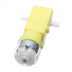
Let's assume you are building a small robot with two DC motors that you need to control.
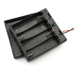
Materials needed:
Connections:
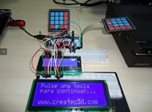
Programming in Arduino: Use the following basic code as a starting point. Adjust the pins according to your connections.
const int enA = 9; // PWM pin for the left motor
const int in1 = 8; // Left direction control
const int in2 = 7; // Left direction control
const int enB = 3; // PWM pin for the right motor
const int in3 = 5; // Right direction control
const int in4 = 4; // Right direction control
void setup() {
pinMode(enA, OUTPUT);
pinMode(in1, OUTPUT);
pinMode(in2, OUTPUT);
pinMode(enB, OUTPUT);
pinMode(in3, OUTPUT);
pinMode(in4, OUTPUT);
}
void loop() {
// Move forward
digitalWrite(in1, HIGH);
digitalWrite(in2, LOW);
digitalWrite(in3, HIGH);
digitalWrite(in4, LOW);
// Control the speed (adjust as needed)
analogWrite(enA, 150);
analogWrite(enB, 150);
delay(2000);
// Keep the direction for 2 seconds
// Move backward
digitalWrite(in1, LOW);
digitalWrite(in2, HIGH);
digitalWrite(in3, LOW);
digitalWrite(in4, HIGH);
delay(2000); // Keep the direction for 2 seconds
}
This module has a built-in 5v power supply, when the driving voltage is 7v-35v, this supply is suitable for power supply, DO NOT input voltage to +5v supply interface, however ledding out 5v for external use is available.
You might also like